
 Material Add Turned Solid/Shell Element
- General Overview
- Step-By-Step
- Tips and Tricks
- Related Tools
![]() Copy, Paste, Save, Load buttons:
Copy, Paste, Save, Load buttons:
- The position of these "form" buttons on the window tells you what settings they apply to. Click here for more information.
- You can
 Copy the settings on this window, then
  Paste those settings to a different edit window of the same type.
- You can
 Save the settings on this window to a file stored in a global folder that is used by your current version of SDS2. Give the file a name that will help other users identify its purpose. You can
  Load a saved file to replace the settings on this window (except Piecemark) with the settings that are stored in the file you select.
- When editing multiple windows at the same time, Paste and Load replace mixed entries to a single field with a single entry. Copy and Save ignore fields with mixed entries, treating them as if they have no entry or do not exist.
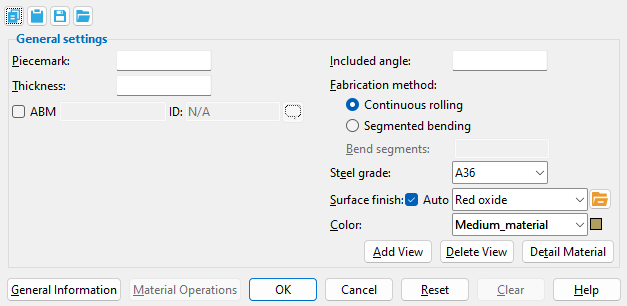
------ General settings ------
Piecemark: Blank or any character string (up to 61 characters). This is the submaterial piecemark .
If this field is left ' blank ', then when this material is generated (after you press " OK "), SDS2 piecemarking looks for materials in the current Job that are physically identical to this material and assigns to this material the same mark assigned to those materials. If no matching materials are found, the material is assigned the material mark prefix for " Miscellaneous ."
Any character string that you enter must be unique. Validation does not let you enter a piecemark that has already been assigned to materials. If you are adding a turned element material a piecemark entered here only applies if the material you are adding is unique -- if the material is exactly the same as previously added materials, the new material gets the piecemark of those previously added materials. On the other hand, if you are editing the material, all materials that are exactly like the material are re-assigned the unique mark you enter when the material is generated (after you press " OK "). The piecemark you enter remains a system piecemark , which means that it may be changed if you later edit a material just like this one and give that material a different piecemark.
Tip: If you want to change a submaterial mark, you should use Rename Project Items in Utility Options . That way all references to the submaterial mark are changed throughout the your current Job, even in Drawing Editor drawings.
Note: A submaterial mark is not yet assigned when this window opens for an add material operation. A piecemark is shown when you Edit Material or Review 2D Items . For the current quantity of materials assigned this piecemark, see the " Current quantity " listed on this material's General Information window.
Report Writer: MemberMaterial.Material.MinorMark
Advanced Selection: MinorMark
Parametric module: MinorMark
Thickness: The wall thickness (in the primary dimension " Units " or other units ) of the turned shell element. This does not apply to turned solid elements.
Included angle: The number of degrees of turning that you want applied when you are Adding a turned element.
Fabrication method: Continuous rolling or Segmented bending .
' Continuous rolling ' results in the turned solid/shell element being generated with a smooth, continuous surface.
' Segmented bending ' requires that you specify a number of " Bend segments ."
Bend segments: The quantity of bend segments used ' Continuous rolling ' is the " Fabrication method ."
Steel grade: A36 or A572 or etc. The grade of steel for the turned solid/shell element whose settings are defined on this window.
Setup: If the steel grade you want is not on the list box (
) for this field, you can use Home > Project Settings > Job > Material Grades > Steel Grades for Plates & Bar Stock to add it to the list.
Tip: Changing " Steel grade " " Color " and " Surface finish " do not cause the material to be regenerated. This means that, if you change those settings only, material operations such as a Cut on Plane may, optionally, be preserved.
Report Writer: MemberMaterial.Material.SubMaterial.MaterialGradeDescription
Advanced Selection: MaterialGrade
Parametric module: MaterialGrade
Surface finish: None or Sandblasted or Red oxide or Yellow zinc or Gray oxide or Blued steel or Galvanized or Duplex Coating or Undefined 1 or Undefined 2 or Undefined 3 or Red oxide 2 or Any user added surface finish. This affects the colors of Solid members on erection views in the Drawing Editor . This also sets the color when Output material color is set to Surface finish for a VRML Export or a DWG/DXF Export. The Color (not Surface finish) sets the color of this material in Modeling .
| sand blasted | red oxide | yellow zinc | user surface finish 1 |
| gray oxide | blued steel | galvanized | user surface finish 2 |
To assign a different surface finish, you can drop-down the current surface finish and select the one you want, or you can press the
Auto ![]() or
or ![]()
If this box
is checked, the material surface finish follows what is set on the member level.
If the box
is not checked, the material surface finish can be changed to whatever is available in the list of surface finishes. If the surface finish changes from what the member level has set, the auto checkbox will be unchecked automatically. When the auto check box is unchecked, the member edit window shows an information tag which notifies the user that an attached material is not following what was set on the member level.
Note 1: Submaterial piecemarks can be split apart by surface finish. All surface finishes that do not have the Break Marks Material checked on can be applied to any like material with out the material splitting. If the Break Marks Material is checked on then only like materials with that specific surface finish can have the same piecemark, and because the submaterial marks differ so would the member's piecemark.
Note 2: When exporting a KISS file using "model" as the Data source surface finish data on the materials are compiled into the KISS download as follows, with a few exceptions (G=galvanized, N= none or sandblasted, P= others). Those exceptions are:
If the box for Finish routing in KISS export setup is set to a user routing
If the user has adjusted the Abbreviation for any of the default provided surface finishes
If you are using a user added surface finish
In these cases you will get what is provided in either the User routing, or the abbreviation field. For other exports it will always provide the abbreviation in the 'surface finishes' settings page.
Tip 1: Surface area is reported on the General Information window -- and this can be used to estimate the amount of coating required and its cost.
Tip 2: Changing Steel grade, Color, and Surface finish do not cause the plate to be regenerated. This means that, if you change those settings only, material fit operations such as a Fit Exact may optionally be preserved.
Report Writer: MemberMaterial.Material.SurfaceFinish
Setup: Surface Finish Settings
Color: A predefined color or a Custom Color . This is the approximate color of the turned solid/shell element when it is displayed in one of the three solid forms .
The predefined colors are set up on the Predefined Colors window. The color swatch next to the list box (
Select ' Custom Color ' (last choice on the list) to launch your operating system's color picker and define any color you like.
Tip 1: Different colors may be assigned to materials that have the same submaterial piecemark .
Tip 2: Changing " Steel grade " " Color " and " Surface finish " do not cause the material to be regenerated. This means that, if you change those settings only, material operations such as a Cut on Plane may, optionally, be preserved.
Report Writer: MemberMaterial.Material.MaterialColor3dRed
Report Writer: MemberMaterial.Material.MaterialColor3dGreen
Report Writer: MemberMaterial.Material.MaterialColor3dBlue
| Special Buttons for Detailing this Material (these do not appear for Add operations) |
||
|
|
|
|
| This button opens a window with a list of preset views . Each preset view that you select on this list is drawn on the submaterial detail when you Detail Submaterial . | This button opens a list of views you can delete. If the material has only one view, you get a warning instead of a list of views since you cannot delete the current view. | This button does a Detail Submaterial on this material. Newly added views are drawn on the detail. Deleted views are not drawn. |
General Information opens the General Information window, which provides additional information and settings that pertain to this material.
Tip: You can use the General Information window to change the material's X, Y, or Z global coordinates (and thus reposition the material within the 3D model).
Also: A Properties button at the bottom of the General Information window lets you Edit Properties for this material.
Material Operations opens the Material Operations window.
Tip: You can use the Material Operations window to delete or edit a stored material operation.
Note: Not all material operations are stored in the Material Operations window. Material Fit Exact, Material Fit Cope, Material Fit Notch, and Cut Layout are the only material operations that are stored here.
OK (or the Enter key) closes this window and applies the settings on it to the material(s).
Defaults: Even if you did not make any changes on this window, pressing OK causes many of the General settings on this window to be applied as the defaults for the next material of the same type that is added in your current session of Modeling.
If you opened this window to edit a single material (single-edit), the Change All Options & Warning List opens after you press the OK button. You can use that window to cancel your changes or, if other materials with the same submaterial piecemark exist, apply your changes to those other materials. Also, if a Cut On Plane or related cutting/bending/fit operation (that does not get stored in the Material Operations window) was previously done on this material, you are given the option to undo that operation.
If you opened this window to edit multiple materials (multi-edit), the Change All Options & Warning List does not open after you press the OK button. Also, if a Cut On Plane or related cutting/bending/fit operation (that does not get stored in the Material Operations window) was previously done on this material, you are not given the option to undo that operation.
Cancel (or the Esc key) closes this window without saving any changes.
Possibilities: If you are adding a new material, Cancel brings you back to the work point location step (step 2) in the add operation. For an edit material operation, Cancel ends the operation.
Tip: When you open this window to review information only -- and you do not want to set the defaults for the next-added rectangular plate -- the best way to close this window is to press Cancel.
Reset undoes all changes made to this window since you first opened it. The window remains open.
Note: The settings shown on this window when it first opens for the adding of a material are the settings of the last-added or last-edited material of the same type (unless you exit Modeling in the meantime).
Clear fills out this window with default settings when adding material. It is disabled during an Edit Material operation. These are the same defaults that are applied when the first new material is added during a session of Modeling in which no other material of the same type has been edited. For example, Clear automatically selects the default Steel grade and zeros out the all Left/Right End Settings.
1 . Click the Material Add Turned Solid/Shell Element icon, which is pictured above. The icon can be found on the Material page > Add section. Select a member you want to add the material to.
▸ Preselect a Member to enable the Members contextual page and click the Material Add Turned Solid/Shell Element icon found in the Materials/Components section.
Alternative: Invoke Material Add Turned Solid/Shell Element using the Find Tool by searching the command name and clicking the icon, which is pictured above.
Learn more about alternative methods for launching commands.
2 . The status line prompts, "Locate Layout". Locate - Pan - Cancel mouse bindings become active. The Locate contextual page becomes active. Select the appropriate Locate option, then place work points as shown below.
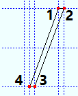
Turned Solid Element:The following illustration shows work points for a turned solid element laid out in a plan view. To finish locating the layout, Left-click locate the final point at the same location as the first point to close the shape of the layout, or middle-click (OK) with your mouse pointer anywhere in the view to automatically do so. The layout must be defined with 3 or more sides, and must create a closed shape.
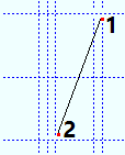
Turned Shell Element: The following illustration shows work points for a turned shell element laid out in a plan view. Unlike " Turned Solid Element ", the layout can have 1 side (2 points). After you have loacted the final point of your layout, middle-click (OK) with your mouse pointer anywhere in the view to finish locating the layout.
2a(optional) : Corner rounding options appear on the Locate contextual page. As you left-click (Locate) to define points, remember to set corner rounding for the most recently located point before you left-click (Locate) to define the next point.
2b (optional) : If you accidentally left-click (Locate) at a point you do not want, hold down Shift and left-click (Remove) to remove that point. You can remove as many points as you like, then continue locating points as described.
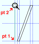
3 . The status line prompts, "Locate the Axis Point". Locate - Pan - Return mouse bindings become active. The Locate contextual page becomes active. Select the appropriate Locate option, then place two points to indicate the axis that the layout from Step 2 will be turned about.
4 . The Turned Solid/Shelled Material window opens.
4a : The options are filled out with default settings that match the last turned element that you added or edited in your current Modeling session. If you did not previously add or edit a turned element, default settings populate the window. Press the "OK" button when you are done with the settings in this window.
Alternative : Press "Cancel" to end the command and stop the turned element material from being added to the model.
5 . The Rotate Material window opens, and a preview of the new turned element is shown on screen. Do one (1) of the following:
Alternative 1:To accept the material's present rotation, press the "OK" button.
Alternative 2 : Change the material's rotational settings and then press "OK" if you want to rotate the material.
Alternative 3 : Press "Cancel" to cancel the command and stop the material from being added to the model.
6 . After pressing "OK" on the Rotate Material window:
Alternative 1: If the material was added to a member without like members, the material is added to the model and the command ends.
Alternative 2: If the material was added to a member with like members, the Material Add -- Options window appears and gives you the option to add the material to like members. After making your choice here and clicking OK, the material is added to the model and the command ends.

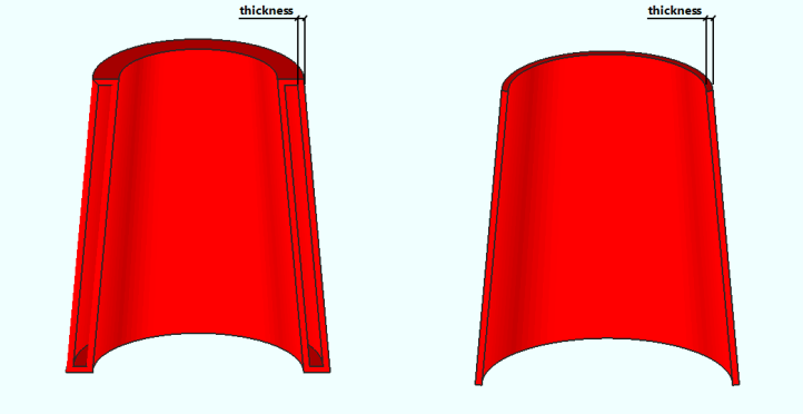
The following illustration shows a turned solid element and a turned shell element that were created using the same layout the turned solid element used. A " Thickness " was not entered for the solid element. The shell element has two walls, each with a user-specified " Thickness ."
- Dimension precision (sets precision for distance entries)
- General Information window (accessible from this window)
- Submaterial piecemark (each unique material identified by)
- Submaterial detail (2D drawing of a material)
- Add Miscellaneous Member
- Miscellaneous Member Edit window (General settings and related topics)
- Miscellaneous Steel (Default misc. member types)
- Legacy Miscellaneous Member Edit window
- Settings on material windows for Add Legacy Miscellaneous Member
- Legacy Miscellaneous Steel (Legacy misc. member types)

